SETUP Tab
TPS
Description
There are 4 fuel maps and 4 timing maps. These 4 maps are broken up into 2 Sets (SET1 and SET2), and within each
set, there are Primary and Alternate maps. The load source setting is the same for both Primary and Alternate
maps within a SET. When the ECU powers up, the load source is set based on the SET1 MAPS LOAD SOURCE setting,
and SET1 Primary maps are active.
- NOTE: These selections DO NOT control map switching! (See OUTPUTS, MAP SWITCHING, SET2 MAPS)
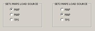
- MAF - Selects the MAF sensor as the load source for fuel and timing maps.
- MAP - Selects the MAP sensor as the load source for fuel and timing maps (speed-density).
- TPS - Selects the TPS sensor as the load source for fuel and timing maps (alpha-N).
TPS to MAP LOAD (Alpha-N) TABLE

- When TPS (Alpha-N) is selected as the load source, this table is used to convert TPS percent to MAP for use as engine load. The MAP value from this table is then used throughout the tune.
[-] SENSORS
MAP SENSOR
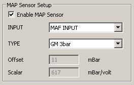
- Enable MAP Sensor - Enabling a MAP sensor enables MAP sensor diagnostics, speed-density tuning, and the ability to use the initial MAP sensor reading as the BARO sensor reading. (See BARO SENSOR)
- INPUT - Select the input where the MAP sensor is connected. This can be the MAF sensor on the ECU (pin 16), or one of the NEMU ADC inputs. (See MAP Sensor Installation)
- TYPE - Specify the type of MAP sensor connected. If your type is not listed, select "Custom" and enter the Offset and Scalar values based on the voltage to MAP conversion for your MAP sensor. If your type IS listed, but you want to modify the conversion parameters, first select your type to set the default parameters, then select "Custom" to modify the parameters.
- Offset and Scalar - If "Custom" type selected, enter the values that satisfy the following equation: mBar=(Scalar*voltage)+Offset
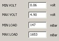
- MIN VOLT - This is the minimum voltage expected from the MAP sensor and is used by MAP sensor diagnostics.
- MAX VOLT - This is the maximum voltage expected from the MAP sensor and is used by MAP sensor diagnostics.
- MIN LOAD - This is the minimum load in mBar expected from the MAP sensor.
- MAX LOAD - This is the maximum load in mBar expected from the MAP sensor.
- MIN LOAD and MAX LOAD are used to calculate MAP percent load which is used by dMAP ACCEL and dMAP DECEL to consistently determine the rate of change in MAP load.
WIDEBAND SETUP
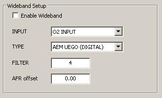
- Enable Wideband - Wideband sensor MUST be enabled to run wideband closed loop.
- INPUT - Select the input where the 0-5V wideband sensor output is connected. This can be the narrow band O2 sensor (O2 INPUT) on the ECU (pin 19), or one of the NEMU ADC inputs.
- If "O2 INPUT" selected, the 0-5V wideband output requires a divide by 2 voltage divider before the narrow band O2 sensor ECU input.
- TYPE - Specify the type of wideband sensor connected.
- FILTER - This sets the input smoothing filter count (max=7). (See Sensor Input Filtering)
- AFR Offset - Ground offsets, and other factors, can cause small errors in the voltage to AFR conversion. Enter any AFR correction necessary here.
IAT SENSOR
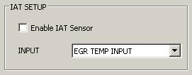
- Enable IAT Sensor - Enabling an IAT sensor enables IAT sensor diagnostics and the IAT sensor reading will be used for all IAT fuel and timing compensations. If not enabled, the DEFAULT TEMP will be used for IAT fuel and timing compensations.
- INPUT - Select the input where the IAT sensor is connected. If "EGR TEMP INPUT" is selected, the IAT sensor can be connected directly and the IAT CONVERSION TABLE should require very if any little adjustment. If one of the NEMU ADC inputs is selected, an external resistor is necessary. (See IAT Sensor Installation)
IAT Sensor Parameters
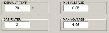
- DEFAULT TEMP - If no IAT sensor is enabled, or the IAT sensor fails diagnostics, this is the IAT that is used.
- IAT FILTER - This sets the input smoothing filter count (max=7). (See Sensor Input Filtering)
- MIN VOLTAGE - This is the minimum voltage expected from the IAT sensor and is used by IAT sensor diagnostics.
- MAX VOLTAGE - This is the maximum voltage expected from the IAT sensor and is used by IAT sensor diagnostics.
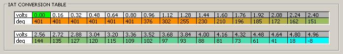
- IAT CONVERSION TABLE - This table is used to convert the voltage from the IAT sensor to temperature. The default table is calibrated for a GM IAT sensor connected to the ECU EGR temperature sensor input ("EGR TEMP INPUT"). It may need some adjustment for your installation, and will need re-calibration for other IAT sensors and/or connection to a MENU ADC input.
ECT SENSOR

- DEFAULT INITIAL VALUE - If the ECT sensor fails diagnostics, the ECT starts at this temperature.
- DEFAULT MAX - If the ECT sensor fails diagnostics, the ECT ends at this temperature.
- If the ECT sensor fails diagnostics, the ECT is set to DEFAULT INITIAL VALUE and is incremented every 6 seconds up to DEFAULT MAX as an emulation of the actual ECT during warmup. If this occurs when the engine is already warmed up, the engine will run rich until the emulated ECT reaches the actual ECT.
- MIN VOLTAGE - This is the minimum voltage expected from the ECT sensor and is used by ECT sensor diagnostics.
- MAX VOLTAGE - This is the maximum voltage expected from the ECT sensor and is used by ECT sensor diagnostics.
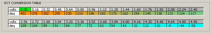
- ECT CONVERSION TABLE - This table is used to convert the voltage from the ECT sensor to temperature. The default table is calibrated for the stock ECT sensor and should need re-calibration only if an after-market ECT sensor is installed.
TPS SENSOR
TPS Parameters
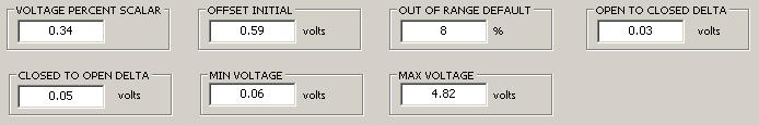
- VOLTAGE PERCENT SCALAR - This is used to convert TPS voltage to percent throttle open (TPS on Data Screen). Use this value to control the 100% throttle open throttle position. If TPS reads less than 100% at full throttle, increase this value until it reads 100%. If TPS reads 100% before full throttle is reached, decrease this value.
- OFFSET INITIAL - This is the initial minimum_TPS_voltage setting. The TPS voltage measured at the sensor should be less than this value when the throttle is closed.
- To reset minimum_TPS_voltage to this value, with ignition on (engine not running), disconnect then re-connect the TPS sensor.
- OUT OF RANGE DEFAULT - If TPS diagnostics determines that the TPS voltage is out of range, the throttle percent is set to this value.
- OPEN TO CLOSED DELTA - If the throttle is currently open, the difference between the current TPS voltage (TPS Voltage on Data Screen) and the minimum_TPS_voltage must be less than or equal this value to consider the throttle closed.
- CLOSED TO OPEN DELTA - If the throttle is currently closed, the difference between the current TPS voltage (TPS Voltage on Data Screen) and the minimum_TPS_voltage must be greater than this to consider the throttle open.
- These values determine the TPS voltage hysteresis between throttle open and throttle closed, to keep the ECU from switching rapidly back and forth between the two.
- MIN VOLTAGE - This is the minimum voltage expected from the TPS and is used by TPS sensor diagnostics to determine if the TPS is out of range.
- MAX VOLTAGE - This is the maximum voltage expected from the TPS and is used by TPS sensor diagnostics to determine if the TPS is out of range.
BARO SENSOR
BARO Sensor Operation
A BARO sensor is used only for BARO FUEL TRIM
and only if the load source is set to TPS (Alpha-N).
The BARO voltage reading can be from 3 different sources:
- BARO sensor connected to a NEMU ADC input
(Electrical connections are same as MAP sensor. See MAP Sensor Wiring). - MAP sensor
- Default value (DEFAULT BARO)
If a BARO sensor is connected and enabled, that is used, otherwise, if a MAP sensor is connected and enable, that is used, provided the ignition switch has been on without cranking the engine for at least 1 second, otherwise the DEFAULT BARO setting is used.
BARO Sensor Setup
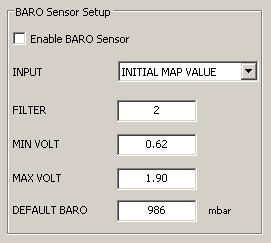
- Enable BARO Sensor - Enabling a BARO sensor enables BARO sensor diagnostics and the BARO sensor reading will be used for BARO fuel compensation. If not enabled, and no MAP sensor is enabled, the DEFAULT BARO value will be used for BARO fuel compensation.
- INPUT - Select the input where the BARO sensor is connected. If using the initial MAP sensor reading for the BARO reading, select "INITIAL MAP VALUE". (Note: Enable MAP Sensor must be set in order to use this setting).
- FILTER - This sets the input smoothing filter count (max=7). (See Sensor Input Filtering)
- MIN VOLT - This is the minimum voltage expected from the BARO sensor and is used by BARO sensor diagnostics.
- MAX VOLT - This is the maximum voltage expected from the BARO sensor and is used by BARO sensor diagnostics.
- DEFAULT BARO - This is the default BARO reading in mBar used if no MAP or BARO sensor is connected and enabled.
MAF|MAP FILTERING
Description
Both MAF and MAP sensors use an adaptive filtering scheme, based on throttle movement and RPM,
where the MAP voltage readings and/or MAF VQ table values are filtered less when quick response is required.
The filtering algorithm is the same as described above in Sensor Input Filtering,
however the filter count is manipulated to increase responsiveness when necessary. If the throttle is
moved above the dTPS FILTER rate, the filter count is reset to MIN FILTER to increase
sensitivity. When the throttle is steady, the filter count is incremented at the INC TIMER rate
back up to MAX FILTER.
MAF|MAP SENSOR FILTERING
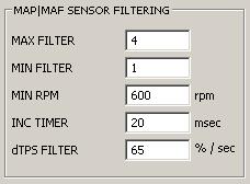
- MAX FILTER - This sets the maximum filter count (max=7).
- MIN FILTER - This sets the minimum filter count.
- MIN RPM - The filter count is reset to MIN FILTER below this RPM.
- INC TIMER - Sets the rate at which the filter count is incremented.
- dTPS FILTER - Determines the throttle closing rate, above which the filter count is reset to MIN FILTER. The throttle opening rate for filter count reset is determined by ACCEL dTPS DEADBAND
[-] EXTRAS
DIAGNOSTICS
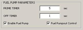
- PRIME TIMER - This sets the amount of time the fuel pump will run when the ignition switch is turned on without cranking.
- OFF TIMER - This sets the amount of time the fuel pump will run after the engine stops turning.
- Enable Fuel Pump - If disabled, the fuel pump will not run. (This has the same affect as pulling the fuel pump fuse.)
- Enable Pumpout Control - If enabled, the fuel pump can be controlled with throttle and gear shift. To initialize pumpout control, place transmission in neutral, open the throttle, then turn ignition ON (do not start), and wait for fuel pump to turn off (PRIME TIMER expired). To arm pumpout control, shift transmission into gear and release throttle (throttle closed). Fuel pump will now turn ON when throttle is opened at least 10%, and OFF when throttle is closed. Shifting transmission to neutral will disarm pumpout control.
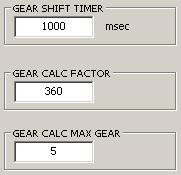
- GEAR SHIFT TIMER - If vehicle speed is greater than 0, gear calculation is suspended for this amount of time when transmission is in neutral. This keeps Gear from changing during a shift.
- GEAR CALC FACTOR - This factor is multiplied by speed and divided by RPM to calculate Gear. If Gear displayed is too high, reduce the factor. If too low, increase factor.
- GEAR CALC MAX GEAR - This must be set to the highet gear in the transmission.
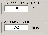
- FLOOD CLEAR TPS LIMIT - If the throttle is opened beyond this limit while cranking, all injectors are disable.
- VSS UPDATE RATE - This controls the rate at which vehicle speed is calculated and is used to calibrate the VSS speed used by the ECU. It has NO effect on the speedometer! If VSS is to high, decrease, if too low, increase this value.
INJECTOR and PLUG ENABLE DIAG
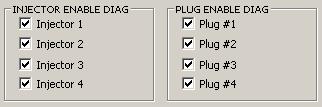
- These are used to disable individual injectors or spark plugs for diagnostic purposes. When a plug
is disabled/re-enabled, the correcponding injector for that cylinder is also disabled/re-enabled. However,
the disabled injector can be re-enabled without re-enabling the corresponding plug.
CAUTION: Enabling an injector with the plug disabled will allow raw unburnt fuel into the exhaust system, which can explode and cause severe damage!.
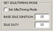
- Set Idle/Timing Mode - Setting this enables "Set Idle Speed and Ignition Timing Mode". While set, with the throttle closed, the ignition timing is held at BASE IDLE IGNITION degrees and the AAC idle speed controler duty is held at IDLE DUTY percent.
- "Set Idle Speed and Ignition Timing Mode" can also be enabled by disconnecting the TPS with transmission in neutral and ECT above 140�F (60�C).
- BASE IDLE IGNITION - Ignition timing is held at this value while Set Idle/Timing Mode is ensbled. Note that this value usually matches the warmed up idle RPM values from the TPS CLOSED TIMING TABLE, but that is not a requirement.
- IDLE DUTY - Idle duty is held at this value while Set Idle/Timing Mode is enabled for setting the idle speed screw in the IACV. With engine fully warmed up, adjust the idle speed screw so the idle RPM is no greater than the minimum value in the Base Target Idle RPM table.
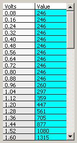
- The MAF VQ table converts the raw voltage from the MAF sensor to a value which represents the mass flow rate (Q) of air entering the engine. This table is specific to each MAF sensor and is updated when a new MAF is selected from the Maf Selection drop down menu.
Maf Selection

- Enable MAF Sensor - This enables MAF sensor diagnostics and calculations. This should be disabled if you are not using a MAF sensor.
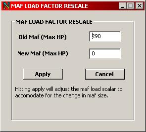
- MAF SELECT DROP DOWN - This drop down menu allows you to chose from a list of pre-configured MAF VQ tables for most of the common factory Nissan MAF sensors. When you select a new MAF from this drop down you will be directed to the MAF LOAD FACTOR RESCALE) dialog.
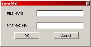
- SAVE MAF - This function allows you to save a custom VQ table curve. It will open the "Save Maf" dialog where you should enter a name for your custom MAF and a maximum HP for your MAF. Select "OK" and it will add your new VQ table to the drop down list and generate a new VQ table file (VQD) for your custom MAF.
- MAF LOAD FACTOR RESCALE - This function allows you to recale the
MAF LOAD FACTOR by entering your current, or old, and new max HP values for your
MAF sensor. The rescale function should only be used when changing your MAF sensor.
- The new MAF LOAD FACTOR is calculated as follows:
PARAMETERS
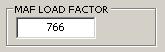
- MAF LOAD FACTOR - This factor is used to calculate MAF Load and therefore effectively scales the MAF load scales on the fuel and timing maps. When changing to a larger MAF sensor, this value is modified by the HP ratio of the old and new MAF sensors to maintain the MAF load scales and avoid having to rescale the fuel and timing maps, along with all the other tables and parameters that utilize MAF Load. If MAF Load never reaches the upper limit of the load scales, this value can be increased manually. By the same token, If MAF Load goes beyond the upper limit of the load scales, this value can be decreased, or the load scales expanded.

- ACCEL MAX MAF LOAD - When the throttle is opened quickly, a large portion of air meassured by the MAF sensor is used just to fill the intake manifold, which causes the MAF Load calculation to be artificially large. Values from this table limit MAF load under this condition to keep from over enrichening the AFR.

- DECEL MIN MAF LOAD - At closed, and very low, throttle opening, and during overrun, the calculated MAF Load can be very low and/or unstable. This table is used to keep MAF Load stable under these circumstances, and to prevent extremely lean conditions during the transition to idle. If the idle RPM drops below the current Target Idle RPM before becomming steady, incresing the values in this table in the appropriate RPM range can prevent this.
DECEL MIN MAF LOAD FUEL CUT COMP TABLE

- DECEL MIN MAF LOAD FUEL CUT COMP - When overrun fuel cut turns off, the value from this table, based on ECT, is added to the value from the DECEL MIN MAF LOAD table for extra enrichment to compensate for the lean condition caused by overrun fuel cut.
DECEL MIN MAF LOAD FUEL CUT COMP DURATION
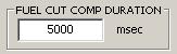
- FUEL CUT COMP DURATION - This sets the maximum amount of time that DECEL MIN MAF LOAD FUEL CUT COMP is applied to DECEL MIN MAF LOAD.
IDLE SMOOTHING
Idle MAF Load Smoothing Parameters
In addition to MAF VQ Table Value Filtering, MAF load is also smoothed
when the throttle is closed to help maintain a steady idle.
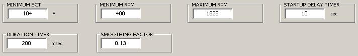
- MIN ECT - ECT must be at least this value to enable smoothing.
- MIN RPM - RPM must be at least this value to enable smoothing.
- MAX RPM - Smoothing is disabled above this RPM.
- STARTUP DELAY TIMER - No smoothing is performed until the engine has been running for at least this amount of time.
- DURATION TIMER - Once smoothing is enabled, it will continue for at least this amount of time.
- SMOOTHING FACTOR - Sets the percentage of the new MAF load value applied to the
current load according to this function:
new_current_load = (new_load*smoothing_factor) + (current_load*(1-smoothing_factor))
Increase this value to decrease the amount of smoothing.
[-] FLEX FUEL
FLEX FUEL SETUP
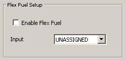
- Enable Flex Fuel - Enables the application of flex fuel ignition, fuel, and boost compensation.
- Input - Selects the NEMU ADC input where the flex fuel sensor is connected.
- Note that the input can be selected without enabling compensation to log and analyze the flex fuel values before they are actually applied.
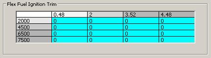
- Flex Fuel Ignition Trim - Values in this table set ignition advance based on flex fuel voltage and RPM. Both flex fuel voltage and RPM scales can be edited.

- Flex Fuel Fuel Trim - Values in this table are enrichment factors applied to IPW based on flex fuel voltage.

- Flex Fuel Boost Trim - Values in this table are added to boost duty based on flex fuel voltage.