OUTPUTS Tab
Trigger ON/OFF Limits:
The ON limit and OFF limit parameters for the triggers are interpreted as follows:
ON > OFF : TRUE if current value above or equal ON limit,
FALSE if current value below or equal OFF limit (on above, off below)
ie: When the trigger value rises to the ON limit, the test is TRUE until the
trigger value falls back below the OFF limit. ON limit - OFF limit = hysteresis.
ON = OFF : TRUE if current value equals ON limit,
FALSE if current value not equal ON limit (only)
This is used only with the GEAR trigger to specify one particular gear.
ON < OFF : TRUE if current value above or equal ON limit,
FALSE if current value below ON limit or above or equal OFF limit (range)
ie: When the trigger value rises to the ON limit, the test is TRUE until the
value either continues to rise to the OFF limit, or falls back below the ON limit.
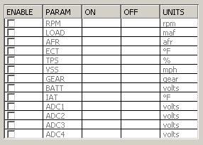
- RPM - RPM.
- LOAD - Load based on current load source.
- AFR - Air Fuel Ratio.
- ECT - Engine Coolant Temperature.
- TPS - Throttle Position Sensor percent.
- VSS - Vehicle Speed Sensor.
- GEAR - Gear.
- BATT - Battery Voltage.
- IAT - Intake Air Temparature after IAT DENSITY CORRECTION
- ADC1 - NEMU Analog input. (With a pullup resistor, these can also be used as a switched input).
- ADC2 - ADC4 - Same as ADC1.
[-] NITROUS
SETUP
NITROUS OUTPUT SETUP
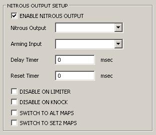
- ENABLE NITROUS OUTPUT - Enables nitrous output programming.
- Nitrous Output - Select the output connected to the nitrous solenoid.
- Arming Input - Optional
- Delay Timer - All enabled triggers must be satisfied for this amount of time to turn output ON.
- Reset Timer - When all enabled triggers are satisfied, the Delay Timer starts. The Delay Timer will continue to run unless any trigger is FALSE for this amount of time.
- DISABLE ON LIMITER - Set this flag to turn output OFF if a rev limiter is hit.
- DISABLE ON KNOCK - Set this flag to turn output OFF if knock is detected.
- SWITCH TO ALT MAPS - Set this flag to switch to Alternate Maps when the output is ON.
- SWITCH TO SET2 MAPS - Set this flag to switch to Set2 Maps when the output is ON.
NITROUS OUTPUT TRIGGERS - See Output Triggers Programming
FUEL AND IGN
NITROUS FUEL COMPENSATION TABLE
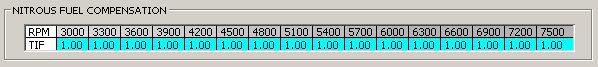
- NITROUS FUEL COMPENSATION - This table contains fuel enrichment factors, based on RPM, that are applied only when the Nitrous output is ON. The RPM scale can be edited.
NITROUS IGNITION COMPENSATION TABLE
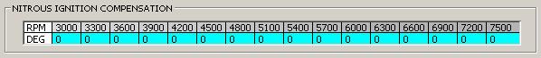
- NITROUS IGNITION COMPENSATION - This table contains ignition advance (+) or retard (-) degrees, based on RPM, that are applied only when the Nitrous output is ON. The RPM scale can be edited.
[-] MAP SWITCHING
ALTERNATE MAPS
ALTERNATE MAP SWITCHING SETUP
The Primary Maps are the default on startup. Use this screen to program switching to the
Alternate Maps. When all enabled triggers are satisfied, the Alternate Maps are in use. If
any trigger is not satisfied, the Primary Maps are in use.
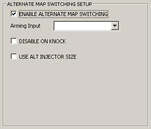
- ENABLE ALTERNATE MAP SWITCHING - Enables Alternate Map switching programming.
- Arming Input - Optional.
- DISABLE ON KNOCK - Set this flag to revert to Primary Maps when knock is detected.
- USE ALT INJECTOR SIZE - Set this flag to use the ALTERNATE INJECTOR SIZE when switched to the Alternate Maps.
ALT MAP SWITCHING TRIGGERS - See Output Triggers Programming
SET2 MAP SWITCHING SETUP
The Set1 Maps are the default on startup. Use this screen to program switching to the
Set2 Maps. When all enabled triggers are satisfied, the Set2 Maps are in use. If
any trigger is not satisfied, the Set1 Maps are in use. Note that the load source is
also switched based on the SET1 and SET2 MAPS LOAD SOURCE
settings.
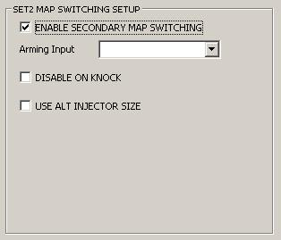
- ENABLE SET2 MAP SWITCHING - Enables Set2 map switching programming.
- DISABLE ON KNOCK - Set this flag to revert to Set1 Maps when knock is detected
- USE ALT INJECTOR SIZE - Set this flag to use the ALTERNATE INJECTOR SIZE when switched to the Set2 Maps.
SET2 MAP SWITCHING TRIGGERS - See Output Triggers Programming
[-] MIL WARNING INDICATOR
MIL SETUP
MIL WARNING INDICATOR
Use this screen to program the MIL in the instrument cluster to turn ON under the specified
conditions. The MIL will still operate normally (ON for bulb check) when the ignition is turned
on, and will turn OFF when the engine is cranked, provided the enabled triggers are not satisfied.
Note also that if MIL programming is enabled, the MIL will NOT turn on when a DTC flag is set,
however the ECU diagnostic mode can still be used to blink the MIL for any DTC flags that are set.
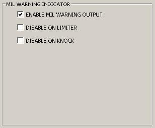
- ENABLE MIL WARNING OUTPUT - Enables MIL warning programming.
- DISABLE ON LIMITER - Set this flag to turn MIL OFF if a rev limiter is hit.
- DISABLE ON KNOCK - Set this flag to turn MIL OFF if knock is detected.
MIL OUTPUT TRIGGERS - See Output Triggers Programming
GENERIC OUTPUT1 SETUP
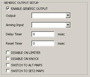
- ENABLE GENERIC OUTPUT - Enables generic output1 programming.
- Output - Select the output to be programmed.
- Arming Input - Optional
- Delay Timer - All enabled triggers must be satisfied for this amount of time to turn output ON.
- Reset Timer - When all enabled triggers are satisfied, the Delay Timer starts. The Delay Timer will continue to run unless any trigger is FALSE for this amount of time.
- DISABLE ON LIMITER - Set this flag to turn output OFF if a rev limiter is hit.
- DISABLE ON KNOCK - Set this flag to turn output OFF if knock is detected.
- SWITCH TO ALT MAPS - Set this flag to switch to Alternate Maps when the output is ON.
- SWITCH TO SET2 MAPS - Set this flag to switch to Set2 Maps when the output is ON.
GENERIC OUTPUT1 TRIGGERS - See Output Triggers Programming
GO2 SETUP
GENERIC OUTPUT2 SETUP
Same as GENERIC OUTPUT1 SETUP above.
[-] A/C CONTROL
A/C SETUP
A/C OUTPUT CONTROL
When A/C control is enabled, OVERRUN FUEL CUT is affected by
FUEL CUT OFF A/C ON RPM and Base Idle Parameters
are affected by A/C ON MIN RPM.
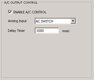
- ENABLE A/C CONTROL - Enables A/C output programming and initializes A/C OUTPUT TRIGGERS to the stock parameters.
- Arming Input - Optional.
- Delay Timer - All enabled triggers must be satisfied for this amount of time to turn A/C compressor output ON. This is important to keep the A/C compressor from being tunred ON and OFF too quickly.
A/C OUTPUT TRIGGERS - See Output Triggers Programming
[-] STOCK FUNCTIONS
STOCK CONTROL
STOCK ECU FUNCTIONS
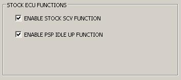
- ENABLE STOCK SCV FUNCTION - Enables stock Swirl Control Valve (SCV) function for KA24E and KA24DE engines.
- ENABLE PSP IDLE UP FUNCTION - Enables Power Steering Pressure (PSP) switch idle duty increase.
RAD FAN CONTROL
Enables radiator fan control for front wheel drive (FWD) vehicles.
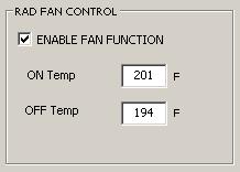
- ENABLE FAN FUNCTION - Enables radiator fan output control.
- ON Temp - Radiator fan ON temperature.
- OFF Temp - Radiator fan OFF temperature.