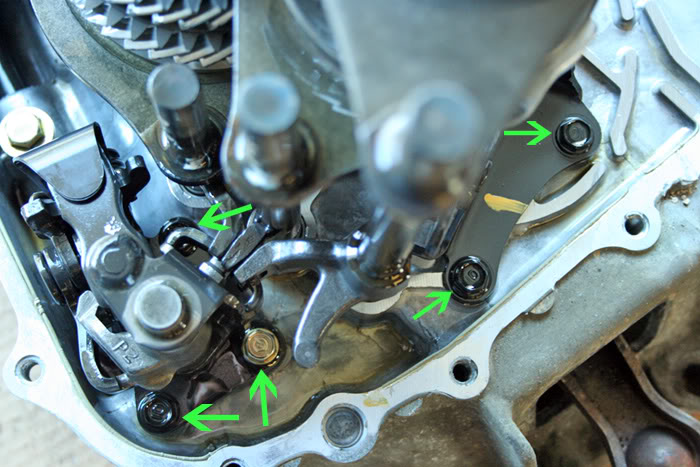
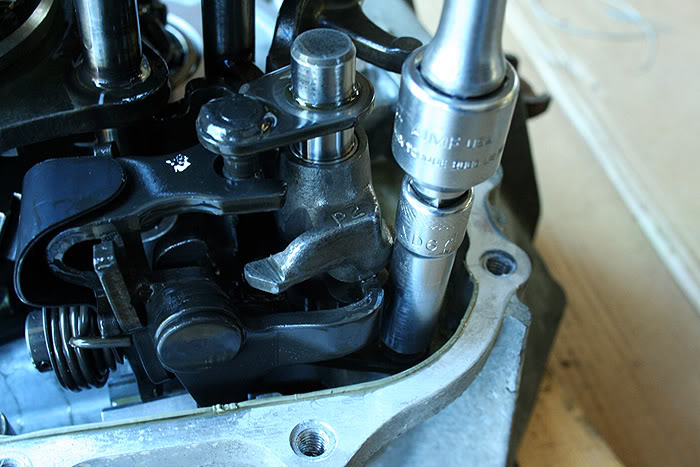
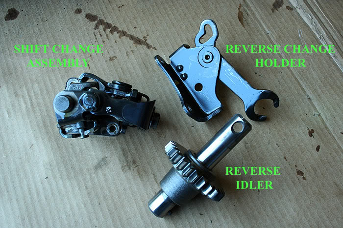
Proceed to remove the 5 10mm bolts (four black and one gold) holding in the shift change assembly and reverse change holder to the bell housing. A thin-walled deep-well socket will make getting to the bolts of the shift change assembly easy. It is difficult with non-deep-well sockets, and almost impossible with wrenches. Then, just lift the two pieces, along with the reverse gear and idler shaft, out of the casing. The shift forks may need to be placed in their neutral settings to make the removal of the shift change assembly in one piece pretty simple.
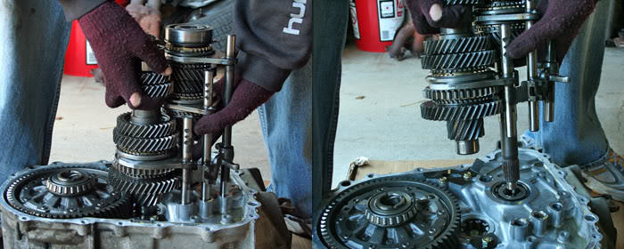
Now, grab the two gear sets and three shift forks with both hands and lift straight up, taking care not to accidentally lose anything from the mainshaft assembly when you lay the gear sets down, as the mainshaft pieces are not held on with a locknut like those of the countershaft. There is also a thrust washer and a shim to be aware of resting at the base of the mainshaft assembly. They will sometimes come out with the mainshaft, and sometimes they will be left behind resting on the casingÆs mainshaft bearing. It is incredibly important to keep these two pieces in their appropriate locations (the thrust washerÆs outward curved surface will rest against the bell housingÆs mainshaft bearing). You can pull these out and place them on the mainshaft again, or just leave them on the bearing.
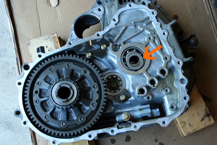
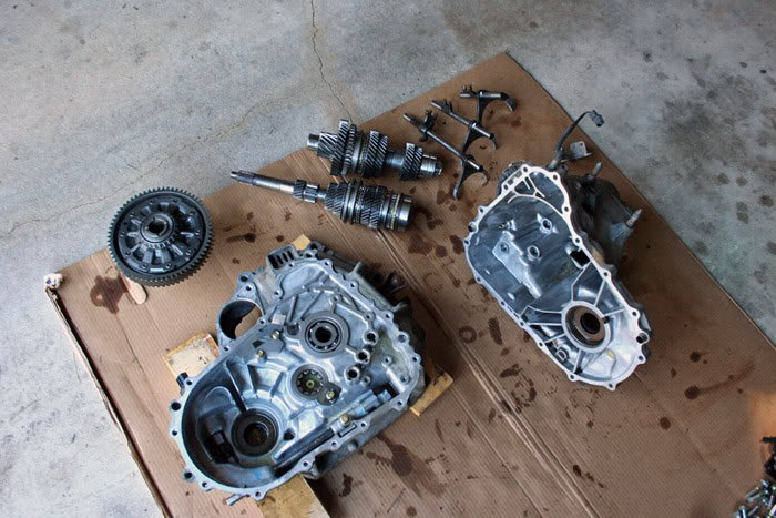
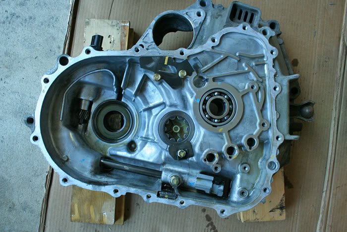
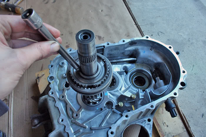
This is the casing torn down to just the bare minimum. Gear sets, differential, reverse idler, shift forks, and change holders have all been removed. Under where the differential was resting, you can also see where the speed sensor locates itself inside the transmission casing. You can now inspect the two bearings in the bell housing for any damage, unusual scarring, or excessive play. Also, the three tabs which hold the shift forks will have quite a bit of play, but they should not have excessive play, when you place the shift forks in them.
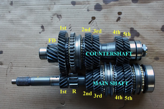
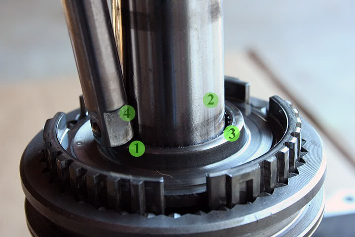
Now, since I am replacing a 3rd gear synchronizer in this transmission, I must pull the mainshaft apart to reach the synchronized 3rd gear in the transmission. By looking at the next photo, you can see why the mainshaft is the gear cluster we are tearing apart to do this. Honda has placed the synchronizer hub for 3rd and 4th gears on the mainshaft ¢ this is the piece between 3rd and 4th gears on the mainshaft. The gold colored piece on the 3rd gear side of this hub is the synchronizer ring that most likely needs replaced.
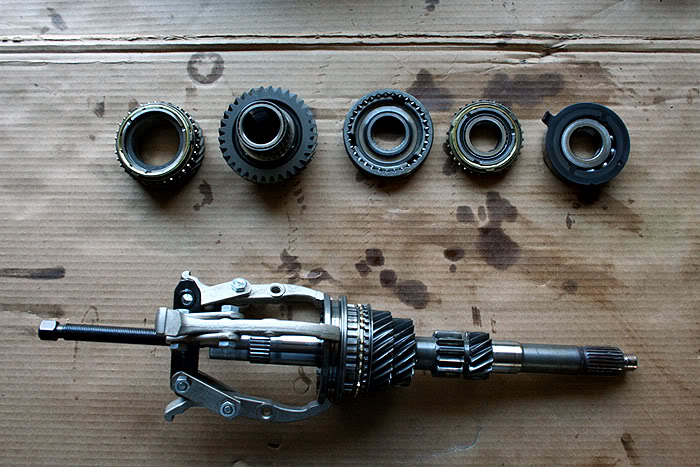
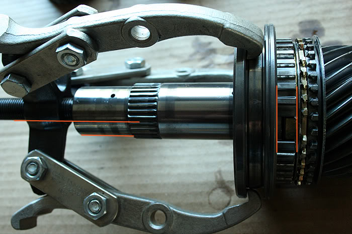
Now, I have already begun pulling pieces off of the mainshaft. DonÆt get too scared or frustrated with this process. Always take your time and stay organized. By following those two basic instructions, you wonÆt lose track of anything. I have removed the pieces and placed them with their tops facing down on the cardboard. When you finally reach the synchronizer hub, you may or may not need a bearing puller. The first two transmissions I ever messed with I did not need one ¢ the synchronizer sleeve and hub slid right off. Every transmission since, however, has required a bearing pulled to remove this piece from the mainshaft. Just make sure the bearing pullerÆs threading bolt is lined up parallel to the mainshaft, and that the bearing pullerÆs arms (I prefer to use a 3-arm bearing puller) are pulling up on the sleeve in such a way that the sleeve remains parallel to the hub. Then twist until it frees up, making sure there is no binding or unusual pressure stiffness as the hub is being removed.
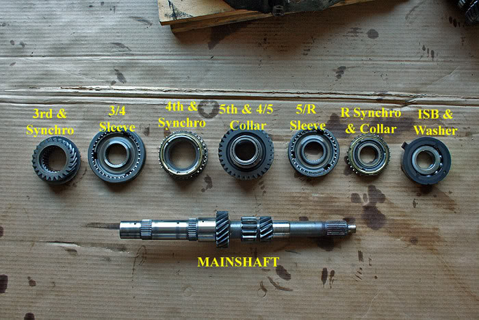
Voila! The mainshaft has been completely disassembled and its parts have been neatly ordered.
We can begin to measure the specified clearance of the synchronizer(s). Pick up 3rd gear and its brass synchronizer ring. Firmly, and evenly, press the ring against the gear. Then simply take a feeler gauge and figure out the gap between the bottom of the synchronizer ring and the gear. IÆm actually replacing this worn down synchronizer ring with another used synchronizer ring which I knew was still in good condition. So I, too, measured the clearance of the replacement synchronizer I had available to double-check. You can visibly see the difference in the gap between the two synchronizers. And the measurement confirms that. The old synchronizer was marginally above service limit, and the replacement synchronizer was in the middle of its acceptable clearance range.
NOTE: This measuring process does not always guarantee a working or worn synchronizer, but usually does offer a good starting point. Even if a synchro is still in the proper range, it, or other parts, can still have wear issues which prevent its proper functioning.

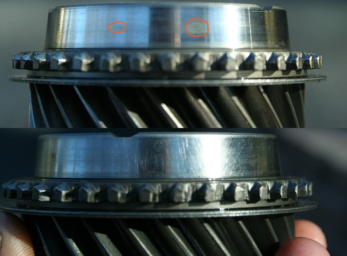
Now, it is time to address the gear cone and the synchronizer sleeve and hub. The gear cone will develop heat spots and wear marks just like a brake disc or a flywheel. In this particular instance, there were several unusual wear marks on the gear cone surface. To ensure the best possible braking surface for the new synchronizer, it helps to scuff the gear cone. Many people use sand paper (500-800 grit) and travel in a circular or crisscross pattern. This is the same idea as resurfacing a flywheel for the installation of a new clutch.
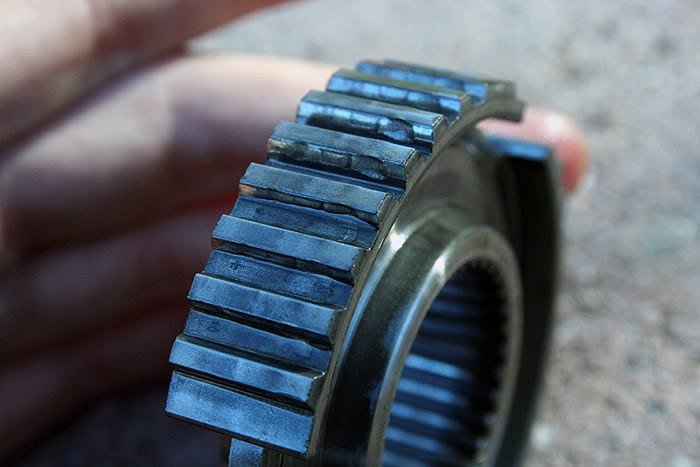
Inspect the synchronizer hub(s) for any wear. Mine unfortunately had pretty bad wear, but I didnÆt have another hub in better condition to use in its place right now. I plan to test this tranny out again: if it still grinds 3rd, IÆll know that this wear on the hub more than likely was the issue.
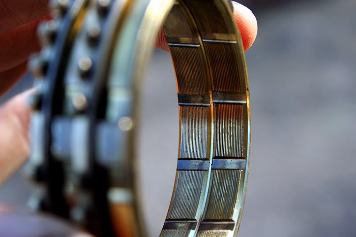
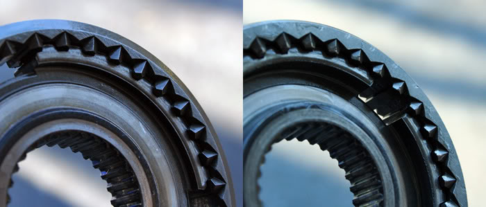
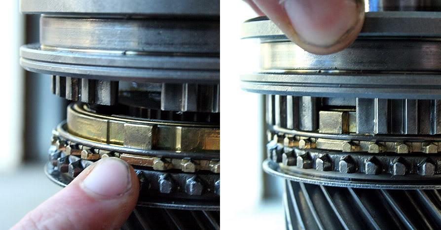
Also, inspect the teeth on the inside of the synchronizer sleeve(s). In this photo, I have the 5th/Reverse synchronizer sleeve to clearly illustrate wear. On the left are the Reverse side teeth. They are full and clearly retain their original edge. On the right is the 5th gear side of the sleeve. It is clearly showing some 75,000+ mile wear and abuse with an operational synchronizer. These can get very, very ugly when a synchronizer has gone bad and the owner continues to use that gear.
Now that inspection of the internal parts is complete, reassembly can now be undertaken. Place the pieces on the shaft in the same manner and order you removed them ¢ 3rd gear needle bearing, 3rd gear, 3rd gear synchronizer and blocking ring, 3rd/4th synchronizer hub and sleeve, 4th gear needle bearing and collar, 4th gear, and so onģ
NOTE: While installing all of the parts on the mainshaft, lubricate all bearing surfaces and bearings with oil. Also, lubricate the gear cones with oil as well. Oil is not necessary on any gear or hubÆs splines that press on over the splines of the main or countershaft.
When you reach the 3rd/4th gear hub, however, you will need to press it on. A press is highly recommended, but you can do this safely a number of different ways. The best alternative to a press is to, using a dead-blow hammer, tap the hub onto the splines of the mainshaft with another pipe or tube that both fits over the mainshaft but on the surface of the hub. I have also made use of a socket extension, lightly tapping on it at alternating points around the hub. The most important thing to do is to make sure that the hub matches up level and evenly to the splines of the mainshaft by pressing the hub down by hand. Then follow this action up with tapping.
While performing this, be aware of the alignment of the synchronizer tabs and the slots for the tabs in the hub.
If there is remaining work to perform on the differential or the countershaft, do it now. Search on here for another thread pertaining to this, or perhaps I may do another tutorial involving these. We now have all of the parts ready to go back together.