BACKGROUND:
The transmission I will go over is my spare 1995 GSR transmission IÆve had lying around for two years now. Luckily, I knew what was wrong with it prior to opening it up this time, as I had it in my car for about two months at one point. It was excellent everywhere, except it ground 3rd at anything above 5500 rpm. So this is what I will set out to fix for this tutorial. I assumed that itÆll be the synchronizer, and have a used one available that I received for doing some transmission work for a friend of mine. So weÆll open it up, inspect various parts, replace the synchronizer, and seal the transmission back up.
TOOL LIST:
The bare minimum you need to simply open the casing up and reseal it:
2x4 blocks of wood (2)
1/2ö ratchet (1)
3/8ö ratchet (1)
10mm 3/8ö deep-well socket (1)
12mm 3/8ö socket (1)
14mm 3/8ö socket (1)
Needle nose pliers (1)
Razor blade (1)
Tube of Honda Bond (1)
8ö - 17öpry bar (2)
Helpful:
3/8ö extensions
1/2ö extensions
Dead-blow mallet (1)
Torque wrench (1)
Magnet (1)
Required to replace synchronizers (mainshaft):
3-arm bearing puller
Required to replace synchronizers (countershaft):
3-arm bearing puller
32mm 1/2ö socket
1/2ö air gun with compressor (or a big breaker bar and some luck) (1)
Bench mounted vice (1)
GENERAL RULE: I have tried to keep all explanations appearing ABOVE the photos posted. If you see a photo and want to see specifically what is being written regarding that photo, scroll up to the first paragraph above.
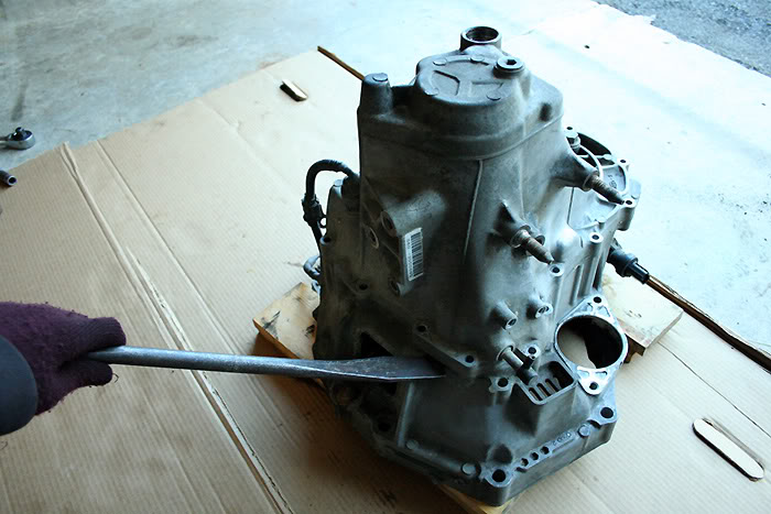
Here you can see the transmission mounted up on two simple blocks of wood. This allows the transmission to be elevated so that the mainshaft does not bottom out against the ground. This is vital for trying to seal up the case at the end of the process.

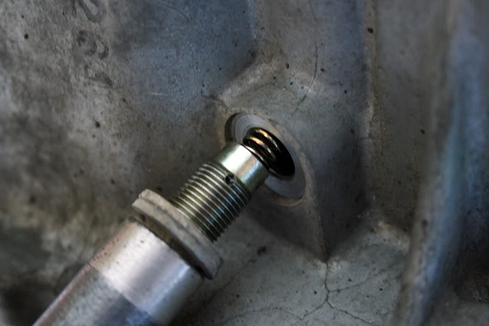
RED ¢ C-clip bolt with 1/2ö socket bolt (1)
PURPLE ¢ 14mm reverse idler gear bolt (1)
GREEN ¢ 12mm bracket bolts (2)
TEAL ¢ 12mm shifter bolts (2)
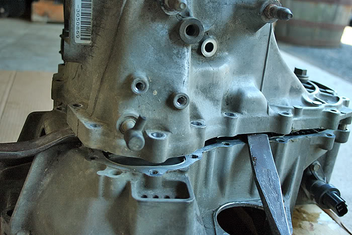
ORANGE ¢ 12mm transmission case bolts (17) ¢ 3 bolts are hidden from view due to the camera angle
Also pictured are the speed sensor, reverse sensor, oil drain plug, and oil fill plug. None of these need removed to proceed.

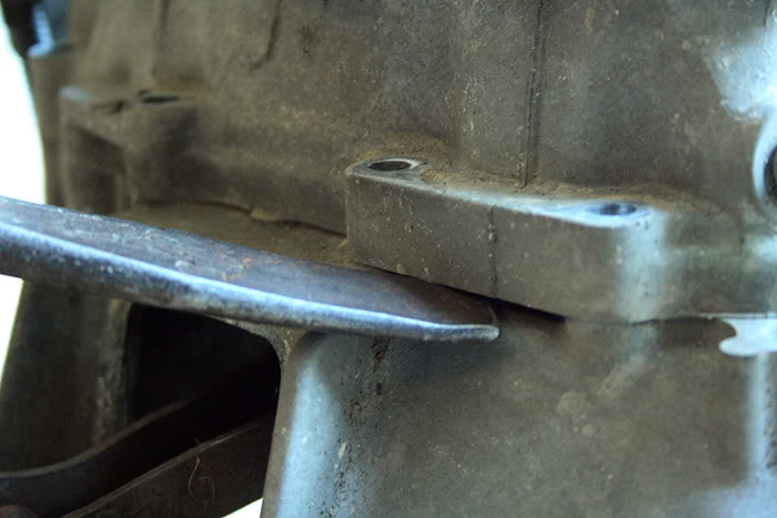
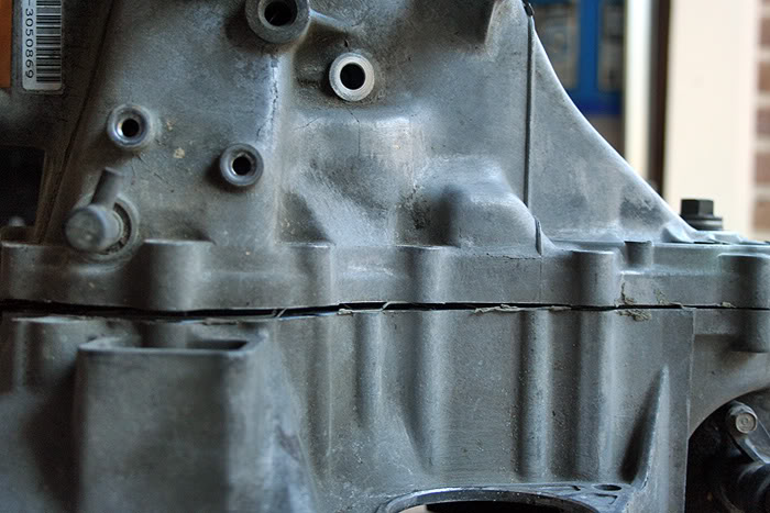
Finish by then removing the remaining 17 12mm bolts (ORANGE ARROWS) which keep the two cases together. Once they are out, you are ready to pry the upper casing from the bell housing. Get a prying mechanism (pry bar, tire iron, etc.) and place one end into the available slot on the front side of the transmission ¢ this unfortunately is the only decent prying point on the B-series and K-series transmission; D-series on the other hand have two pry points.
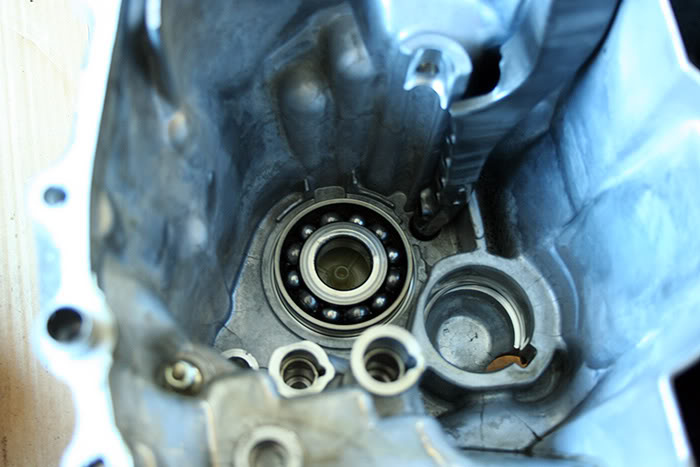
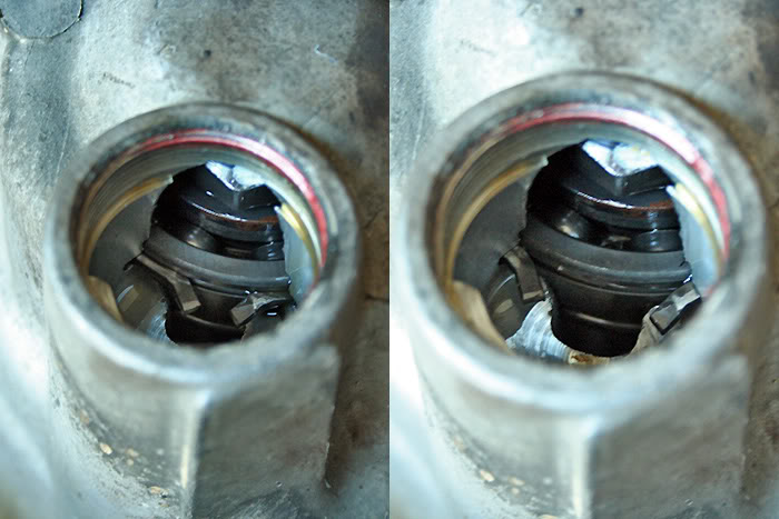
These are the two casing halves separated finally. In the second photo, you can see that the mainshaft bearing has pulled up with the casing. If this happens, tap the casing against the surface you are working on to make the bearing drop out (it is nice to have a towel or something down to catch the bearing with to give it a soft landing).