
- IAT IGNITION TRIM - This table contains ignition trims based on DENSITY CORRECTED IAT that are applied when the throttle is open. Positive values are advance, negative values are retard.

- ECT IGNITION TRIM - This table contains ignition trims based on ECT that are applied when
the throttle is open.
Positive values are advance, negative values are retard.

- ECT IDLE IGNITION TRIM - This table contains ignition trims based on ECT that are applied when
the throttle is closed. Positive values are advance, negative values are retard.
See also Throttle Closed Ignition Timing Table.
(TPSITA is "TPS Ignition Timing Adjustment", or ignition trim due to throttle movement.
See ACCEL IGNITION TRIM Parameters below for TPSITA details.)
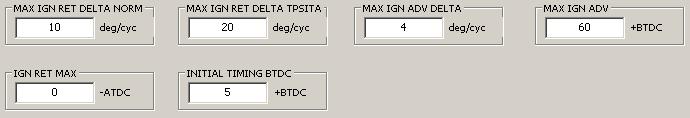
- MAX IGN RETARD DELTA (normal) - This is the maximum number of degrees that the ignition timing is allowed to be retarded per engine cycle. This smooths large ignition retard changes under normal operating conditions.
- MAX IGN RETARD DELTA (TPSITA) - This is the maximum number of degrees that the ignition timing is allowed to be retarded per engine cycle when TPSITA ia active. This allows larger ignition retard changes when TPSITA is active.
- MAX IGN ADVANCE DELTA - This is the maximum number of degrees that the ignition timing is allowed to be advanced per engine cycle. This smooths large ignition advance changes under normal operating conditions.
- MAX IGN ADVANCE - This sets the maximum ignition advance timing before any knock timing adjustment.
- IGN RETARD MAX - This sets the maximum ignition retard timing before any knock timing adjustment.
- INITIAL TIMING BTDC - This sets the initial ignition timing and is what should be displayed for Final IGN on the "Data Screen" with igntion on, engine not running.

- DWELL BATTERY VOLTAGE FACTOR - This table contains factors, based on battery voltage, that are multiplied by dwell to adjust for fluctuations in battery voltage.
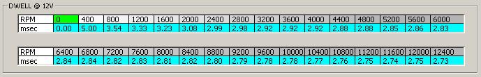
- DWELL @12V - This table contains dwell, or coil charge time, values based on RPM. Values are at a battery voltage of 12.0V, which corresponds to a DWELL BATTERY VOLTAGE FACTOR of 1.00.
If the current knock voltage is greater than the average knock voltage for the current cylinder plus the CYLINDER KNOCK VOLTAGE LIMIT for that cylinder at the curent RPM, the Knock Count is incremented, otherwise the weighted average knock voltage for that cylinder is updated.
Basically the ECU maintains a weighted average noise level (average knock voltage) for each cylinder, and when the noise from a cylinder goes above this level plus the "knock noise limit", knock is detected and the Knock Count is incremented.
The knock_adjustment is increased (advance) or decreased (retard) based on the following:
If knock_adjustment indicates retarded timing, Knock Trim is then set based on knock_adjustment. If engine operation takes it outside the knock analysis zone, and the throttle is still open, Knock Trim is set to the average knock_adjustment while operating in the knock analysis zone.
Finally Knock Trim is checked against the previous adjustment to keep the maximum delta below MAX RETARD DELTA. It is then compared and limited to the knock retard limit from the KNOCK RETARD LIMIT table.
Note that Knock Trim is applied AFTER the IGN RETARD MAX limit is checked!
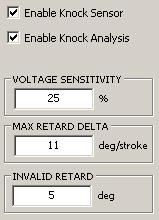
- Enable Knock Sensor - Enables knock sensor diagnostics only. Knock detection still functions if this is disabled.
- Enable Knock Analysis - Enables knock analysis. If disabled, Knock Count is still set, provided a knock sensor is connected.
- VOLTAGE SENSITIVITY - This determines the weighted average knock voltage for each cylinder and is the percentage of the current knock voltage that is applied to the average knock voltage for the current cylinder.
- MAX RETARD DELTA - This limits the number of degrees the ignition can be retarded per stroke.
- INVALID RETARD - If the knock sensor fails diagnostics, the ignition timing is retarded this number of degrees as a safety measure.
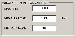
- MAX RPM - Sets knock_zone_max_rpm.
- MIN MAP LOAD - Sets knock_zone_min_load when current load source is MAP.
- MIN MAF LOAD - Sets knock_zone_min_load when current load source is MAF.
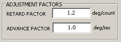
- RETARD FACTOR - This factor is multiplied by the Knock Count to set knock_adjust_retard and controls how much the timing is retarded when a knock event occurs (Knock Count_ > 0). Increase to increase knock timing retard.
- ADVANCE FACTOR - Sets knock_adjust_advance. This value controls the duration of retarded timing for a knock event (timing retarded due to knock). Increase to decrease knock retard duration.
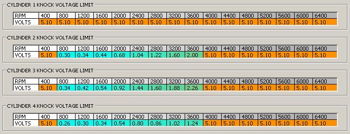
- CYLINDER KNOCK VOLTAGE LIMIT - If the Knock Count at a certain RPM is too sensitive, increase that limit. With another means of knock detection, these tables can be tuned for more precise knock detection.
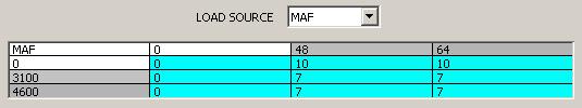
- LOAD SOURCE - Select the active load source when knock analysis is active (engine operating in knock zone of timing map).
- KNOCK RETARD LIMITS - Sets the maximum ignition knock retard based on RPM and load. The load and RPM scales can be edited.
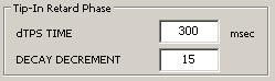
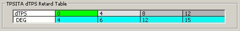
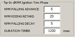
TPSITA occurs in 2 phases. The first phase is called "Tip-In Retard" and is based on TPS opening rate of change (dTPS). This reduces spark knock at throttle tip-in. The second phase is called "Tip-In dRPM Ignition Trim" and is based on RPM rate of change (dRPM). This helps maitain engine power while the RPM is fluctuating as the clutch is engaged.
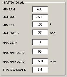
There are a number of criteria that must be met to activate the "Tip-In Retard" phase. If ECT is at least MIN ECT, and vehicle speed is below MAX SPEED, and engine load is below either MAX MAF LOAD or MAX MAP LOAD (depending on the current load source), and the change in TPS percent is at least dTPS DEADBAND, and rpm is above MIN RPM, and no more than MAX RPM, and gear is below or equal MAX GEAR, the "Tip-In Retard" phase is initiated. This initializes the tpsita_decay_factor to its maximum value and starts the tpsita_timer. If the transmission is shifted above MAX GEAR, TPSITA is canceled.
This phase continues until tpsita_timer = DURATION TIMER, at which point TPS Trim is reset to 0.

- CYLINDER 1 IGNITION TRIM - Contains ignition timing trims (positive are advance, negative are retard) for each cylinder based on RPM.
- All other cylinder tables function the same. - .

- CRANKING IGNITION - Ignition timing BTDC based on ECT used while in cranking mode. If cranking RPM is below 100rpm, the timing is retarded by multiplying by rpm/100.