Table of Contents
ADC Box Overview
Top of ADC v2 board
- ADC0-ADC3 - Connect any 0-5 volt sensors (MAP, IAT, WBO2, Oil Pre, etc)
- FLEX - Connect output from GM Flex Fuel Sensor directly to this pin
- 5Vout - 5v power source for MAP or IAT Installs
- GRD- Ground (chassis or ECU) when using the 12Vin and using the 5Vout
- 12Vin - Supply pin with 12V which will be for reference power for the 5Vout

Bottom of ADC v2 board
- 4 sets of solder pads in the bottom center of the board can be jumped for a 4.7k ohm pull up resistor for each ADC0-3 circuit.
- Only use when needed (IAT installs are the most common use for this option)

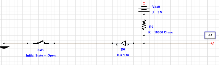
Wiring a switch to an ADC input.
- 2 prong switch (clutch switch/cruise switch or toggle)
- 1k ohm 1/8 watt resistor
- 1 fA Diode
The diode is required if the switch is already wired to a 12V source, such as the E-brake warning light switch. The 5V going to the 10k ohm resistor is from the 5V output in the breakout box.
Vdc0 = 5 volt output from the ADC box.
Wiring a wideband to an ADC input.
The ADC inputs can handle any 0-5 volt wideband output signal.
Find your wideband's 0-5 volt output wire and connect it directly to any of the ADC 0-3 inputs on the breakout board.

Then select the wideband in the drop down list and enable it in the software.
Wiring IAT sensor to ADC input
The IAT sensor is a vital part of any speed density conversion so we tried to make it easier for you guys to install.
The IAT sensor has two wires (polarity does not matter) that need to be ran to the ADC box on most B13 SR20 and S13 KA24 setups. These the ECUs do not support the EGR Temp input like the SR20DET ECUs do.
- Wire ADC 12v input to ECU power source (pin 38)
- Wire ADC Ground input to ECU ground source (pin 39)

- Flip over ADC box and make sure to solder two solder pads together on the corresponding ADC input you would like to use for the IAT input.

- Connect 1 wire from IAT sensor to the ADC (0-3) input pin that corresponds to the jumper you just soldered together.
- Connect remaining wire from IAT sensor to ADC Ground pin
To enable the sensor in the calibration go to SETUP → Sensors → IAT
Also make sure you select the correct calibration for the sensor, you can do this by right clicking on the voltage vs temperature table and selecting the ADC input option.